One System, Three Voltages – Make Sense?
By Pat Brown
“Constant Voltage” Distribution Systems
Constant voltage is a term used to describe a circuit where the voltage from the source is not significantly affected by the presence of the load. It has nothing to do with the actual voltage waveform, especially in a sound system, which can be a sine wave, music, speech, or noise. These voltages are anything but constant. That is why in SynAudCon training we refer to these as transformer-distribution systems in lieu of constant voltage. Since the step-down transformer in the loudspeaker multiplies its impedance to a higher value, transformer-distributed loudspeaker systems are often referred to as using “High-Z” distribution.
Figure 1 shows the signal chain used in SynAudCon’s High-Z system calculator.
Voltages of Interest
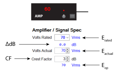
There are three “voltages of interest” in a transformer-distributed loudspeaker system. Differentiating between these voltages is imperative for understanding how these systems work. These and the other variables that determine the amplifier’s output voltage are shown in Figure 2.
The first is the rated voltage, which I will refer to as Erated. This is always a standard value, such as 25 V, 70 V, 100 V, etc. Erated has nothing to do with the actual use of the system. It is reference voltage based on a sine wave, even if one is never played over the system. Erated is always a root mean square (RMS) voltage. This is 0.707 times the peak voltage of the sine wave. It is accepted practice to omit the RMS designation when referring to transformer-distributed loudspeaker systems. In other words, it’s a “70 V” system not a “70.7 VRMS” system. I will omit the use of RMS for the remainder of this article. In the calculator Erated is selected by a drop-down menu (Figure 3).
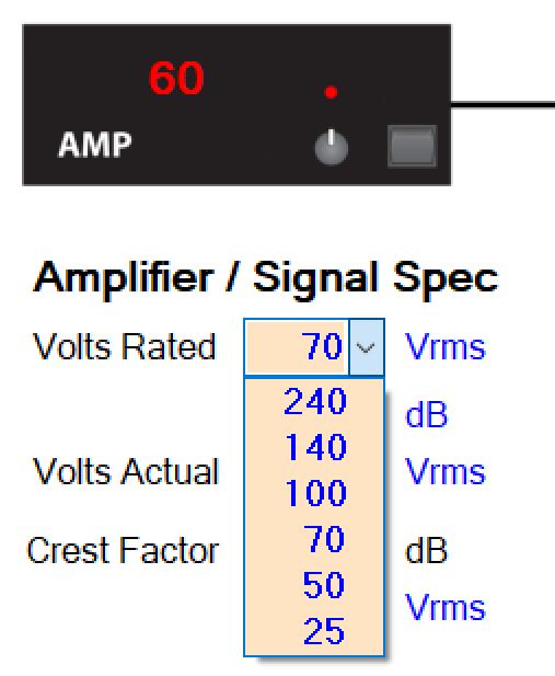
Fig. 3 – The calculator shows the various standard distribution voltages used in transformer-distributed loudspeaker systems.
The second is the actual voltage, which I will refer to as Eactual. In the real world our “70 V” system may deviate from 70 V. Examples include a 70 V amplifier that only produces 65 V, or a “100 V” system driven by a 70 V amplifier. In a textbook perfect world Erated and Eactual are the same, but in practical cases they can be different.
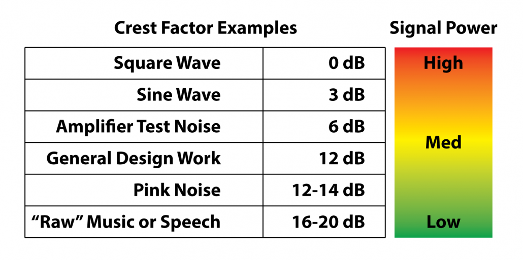
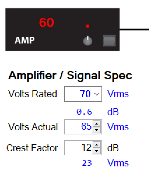
The third voltage of interest is the operational voltage, which I will call Eop. This is the voltage that determines the sound level from the system. It is Eactual modified by the signal crest factor CF. The CF accounts for the fact that real-world audio program material has a lower RMS voltage than the sine wave used to rate these systems. If we fail to account for this our systems will not produce the expected sound level as determined by calculation. A generally accepted CF used for the design of systems of this type is 12 dB. In terms of watts this is the commonly used “1/8-power rating” for a sine (or burst) wave rated amplifier (Figure 4).
More on the Rated Voltage
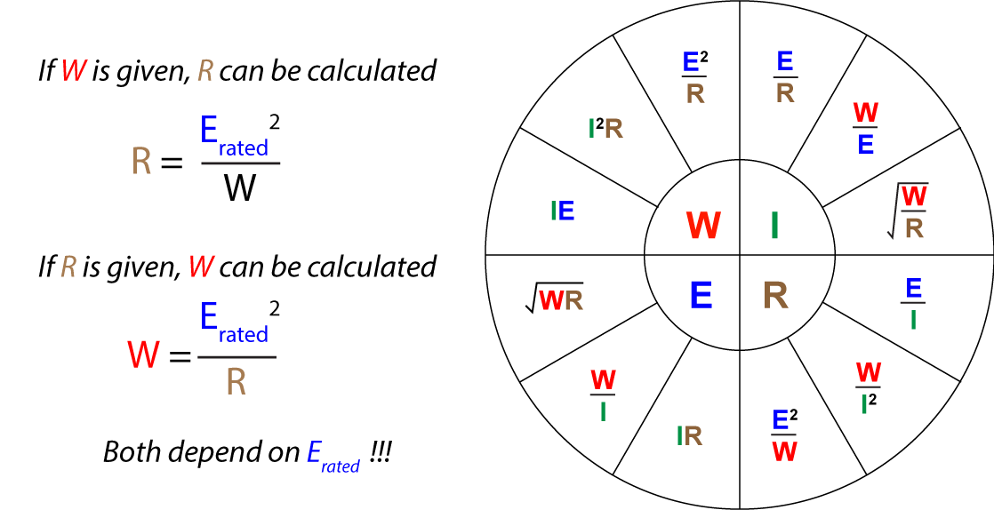
The selection of Erated is a hardware choice. It determines the required amplifier type and the step-down transformers. The power taps on the loudspeaker’s transformer assume the presence of Erated. It is selected by a drop-down menu in the High-Z calculator (Figure 3). A variety of rated voltages are used for these systems, ranging from 25 V to 240 V. I can shop for a “70 V” or “100 V” amplifier and be assured that the amplifier can produce a sine wave at the rated voltage for some meaningful time duration into some rated minimum load. The minimum load may be given as an impedance in ohms or as a power rating in watts. These are mathematically related and two different ways of saying the same thing (Figure 5).
The Erated is determined by the application. In general, systems that use high numbers of loudspeakers and/or long wire runs use higher distribution voltages. There are also building code considerations that drive this choice. Erated does not affect the sound quality of the playback system. A 25 V, 70 V, and 100 V system can sound identical if all are setup to deliver the same voltage to the loudspeaker.
Actual Voltage
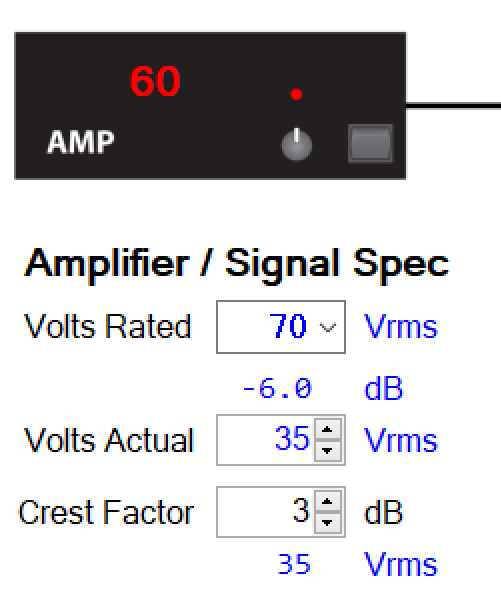
Eactual is a refinement of Erated. The amplifier may have a volume control that allows it to be turned down from its rated voltage. Of course, this has no effect on the step-down transformers in the loudspeakers, so we can have a 70 V system being driven at a lower-than-rated voltage (Figure 6).
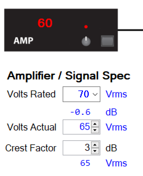
Another example would be a 70 V system (by design) that is driven by a 70 V amplifier that doesn’t quite output 70 V. If the amplifier maxes out at 65 V, the output level of this system will be 0.5 dB lower than expected. If it outputs 90 V it will be 0.5 dB higher than expected. So, Eactual is a way to trim Erated from the standard value assumed by the step-down transformers (Figure 7).
Delta dB
The field between Erated and Eactual shows the dB difference between these two values (Figure 7). In the textbook case they would be equal. Here are a few examples of when they aren’t.
– A 70 V (Erated) amplifier that only produces 65 V (Eactual). The difference is -0.6 dB (Figure 7).
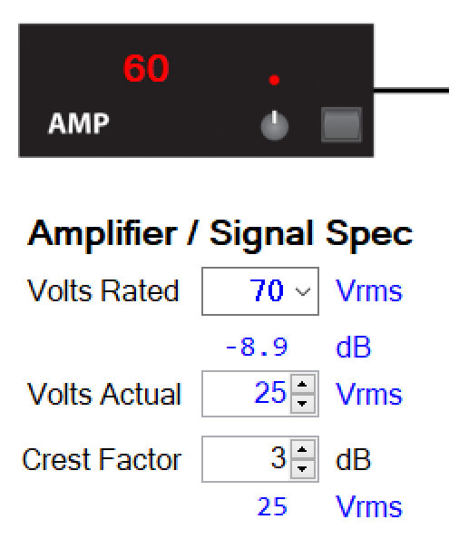
– A 25 V amplifier is used to drive a 70 V system. This system will be -9 dB lower than if a 70 V amplifier were used (Figure 8).
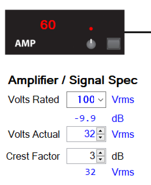
– The volume control on a 100 V amplifier is turned down by 10 dB. While still a “100 V system” the RMS voltage will be about 1/3 that of the system operated at Erated (Figure 9).
Operational Voltage
Erated and Eactual are always based on sine waves and have nothing to do with the actual program material played over the system. This condition represents a worst-case scenario for the amplifier, and it simplifies the math. A sine wave is a continuous tone at the selected voltage. Eactual is modified by CF to produce Eop and the resultant sound pressure level (LP) from the loudspeaker.
The CF value must be appropriate for the application. Making it too high will make it difficult to achieve a target LP without clipping the amplifier. Making it too low may distort the amplifier and/or loudspeakers. As stated earlier 12 dB is a good design guideline.

Fig. 11 – Once the amplifier’s voltage is known, the other variables can be factored in to calculate the LP at the listener.
Conclusion
In this article I have shown the factors that determine the output voltage of the amplifier in a transformer-distributed loudspeaker system. As you can see, these systems seldom output their rated voltage, which is a source of much confusion.
From this point on, any changes to the LP of the system happen post amplifier. The variables include wall-mount attenuators, the step-down transformer in the loudspeaker, the loudspeaker’s sensitivity, the distance to the listener, the number of loudspeakers, and the wire gauge.
I cover these and other details in depth in SynAudCon’s online training Course 110 – Transformer-distributed Loudspeaker Systems. pb


